STM32MP157-M4_Examples
3.2 A7_M4用户态通信
- 设计需求
这里假设需求为A7和M4同时运行,然后A7控制M4操作LED灯,A7和M4的相互唤醒。
3.2.1 基础知识
开放式非对称多处理(Open AsymmetricMulti-Processing,OpenAMP)是一种通用的抽象框架,提供一系列API,实现了构成系统的异构处理器之间上电、加载固件、断电及共享信息(通信)。
OpenAMP 包含了两个关键组件:
-
Remoteproc(Remote Processor Framework):管理框架;
-
RPMsg(Remote Processor Messaging Framework):消息传递框架;
Remoteproc主要作用就是对远程处理器的生命周期进行管理(life cyclemanagement,LCM),即启动、停止远程处理器。前面加载运行M4固件已经体验过了,Cortex-A内核先启动,然后使用LinuxRemoteProc框架进行加载Cortex-M4固件,启动M4内核。STM32MP1的Remoteproc框架如图3.2.1所示。
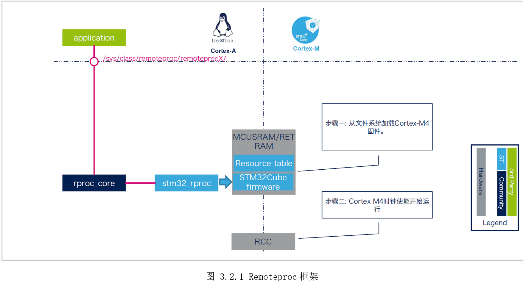
ST官方提供的内核已经默认配置了Remoteproc驱动,进入系统后,首先将要运行的M4固件放在“/lib/firmware/”目录下,然后将固件名字写到“/sys/class/remoteproc/remoteproc0/firmware”,再操作“/sys/class/remoteproc/remoteproc0/state”启动、停止M4处理器。
[root@100ask:~]$ ls /lib/firmware/  //elf固件存放目录
DEMO_LED_CM4.elf
[root@100ask:~]$ echo GPIO_LED_CM4.elf > /sys/class/remoteproc/remoteproc0/firmware  //加载固件
[root@100ask:~]# cat /sys/class/remoteproc/remoteproc0/state  //查看固件状态
Offline  //固件离线状态
[root@100ask:~]# echo start > /sys/class/remoteproc/remoteproc0/state  //启动M4
[22683.222322] remoteproc remoteproc0: powering up m4
[22683.229097] remoteproc remoteproc0: Booting fw image GPIO_LED_CM4.elf, size 1899976
[22683.235549] remoteproc remoteproc0: header-less resource table
[22683.241235] remoteproc remoteproc0: not resource table found for this firmware
[22683.248749] remoteproc remoteproc0: header-less resource table
[22683.254414] remoteproc remoteproc0: remote processor m4 is now up  //远程M4已启动
[root@100ask:~]# echo stop > /sys/class/remoteproc/remoteproc0/state  //停止M4
[22709.281733] remoteproc remoteproc0: warning: remote FW shutdown without ack
[22709.287325] remoteproc remoteproc0: stopped remote processor m4  //远程M4已停止
除了在Linux的用户态控制M4内核的生命周期,还能在Linux内核态使用API控制(参考linux-origin_master/Documentation/remoteproc.txt),甚至U-boot中控制。
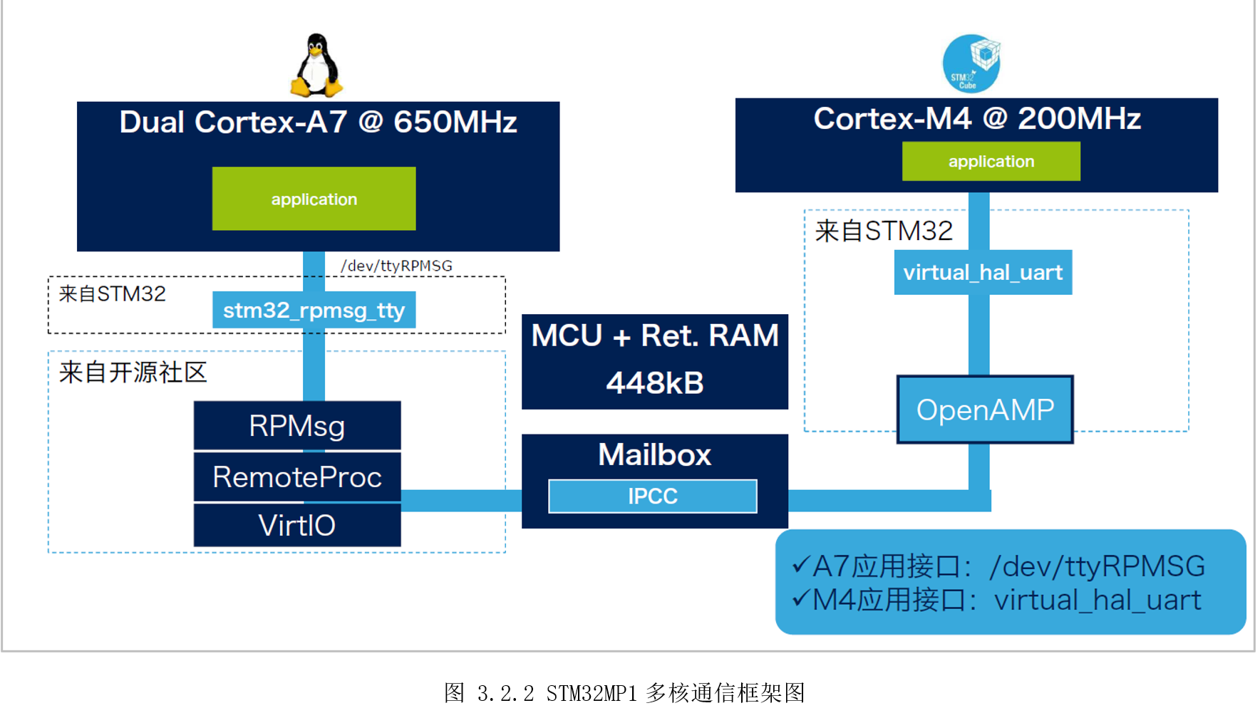
RPMsg是处理器间的消息传输总线,其中每个处理器都是总线上的器件。它允许内核驱动程序与系统上的远程处理器进行通信,同时,驱动程序可以根据需要公开适当的用户空间接口(参考linux-origin_master/Documentation/rpmsg.txt)。RPMsg使用虚拟I/O(Virtio)组件,Virtio可提供虚拟I/O服务,以支持主处理器与远程处理器之间的通信。
STM32MP1多核通信框架如图3.2.2所示。一边是运行Linux的A7,基于RPMsg服务面向Linux用户空间提供“/dev/ttyRPMSG”串口节点收发数据;另一边是运行裸机或RTOS的M4,基于OpenAMP库调用虚拟串口函数“virtual_hal_uart()”收发数据。从两边应用角度来看,如同串口透传,类似A7和M4通过串口连接;从两边硬件角度来看,信号通知(Mailbox)服务基于内部IPCC(Inter-Processorcommunication controller),数据传输基于共享内存。
3.2.2 硬件设计
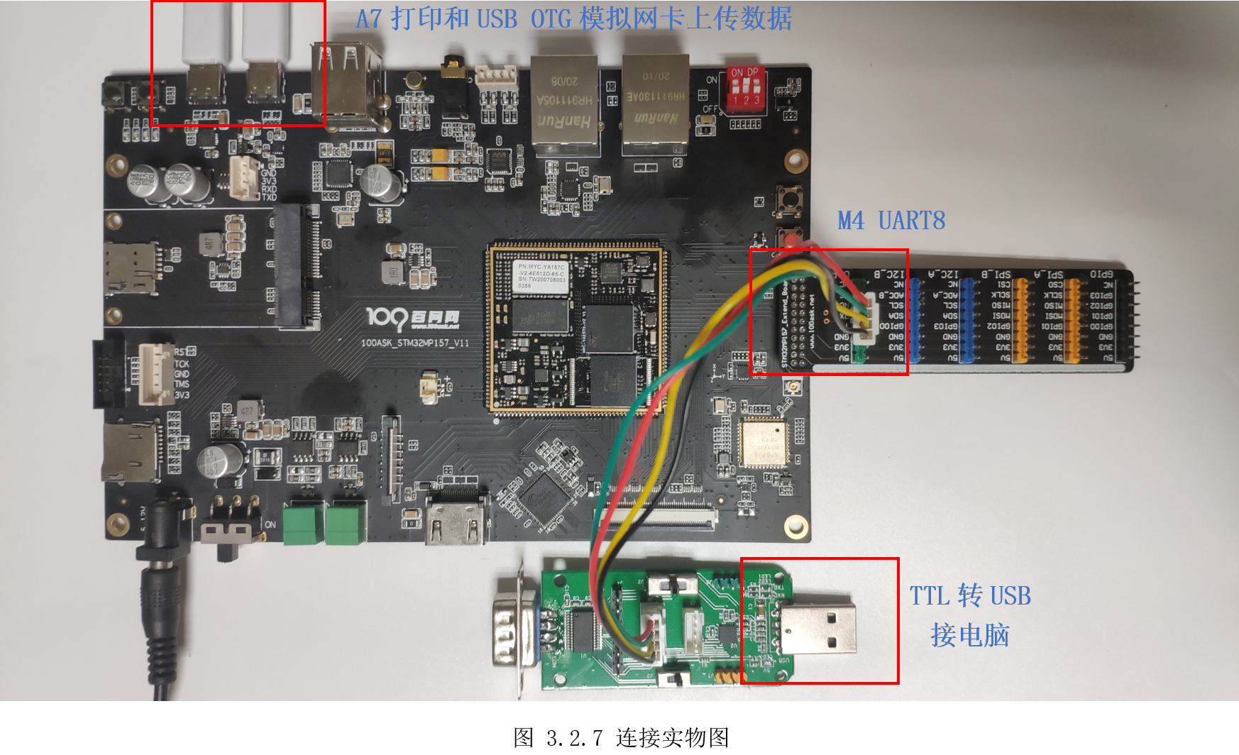
硬件外设需要用到一个LED灯给M4,A7使用UART4,M4使用UART8。UART是开发板默认调试串口,有串口转USB芯片,用户可以直接通过Type-C连接电脑,UART8是在扩展接口,对外提供的是TTL电平,需要用户自行准备TTL转USB模块连接电脑。
3.2.3 MX设置
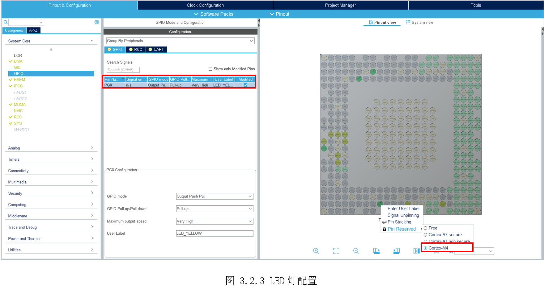
首先配置MCU系统时钟为209MHz,然后配置LED_YELLOW给M4,如图 3.2.3所示配置。
然后将UART8(PE0、PE1)分配给M4,用于M4打印,如图 3.2.4所示。

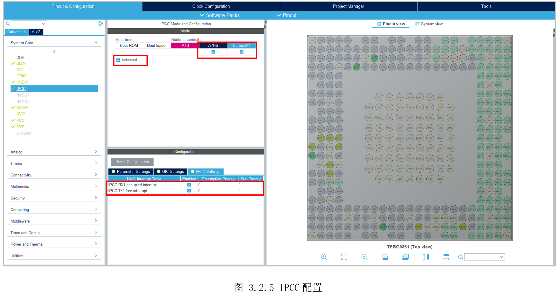
然后配置IPPC,同时给A7和M4,并且使能中断,如图 3.2.5所示。
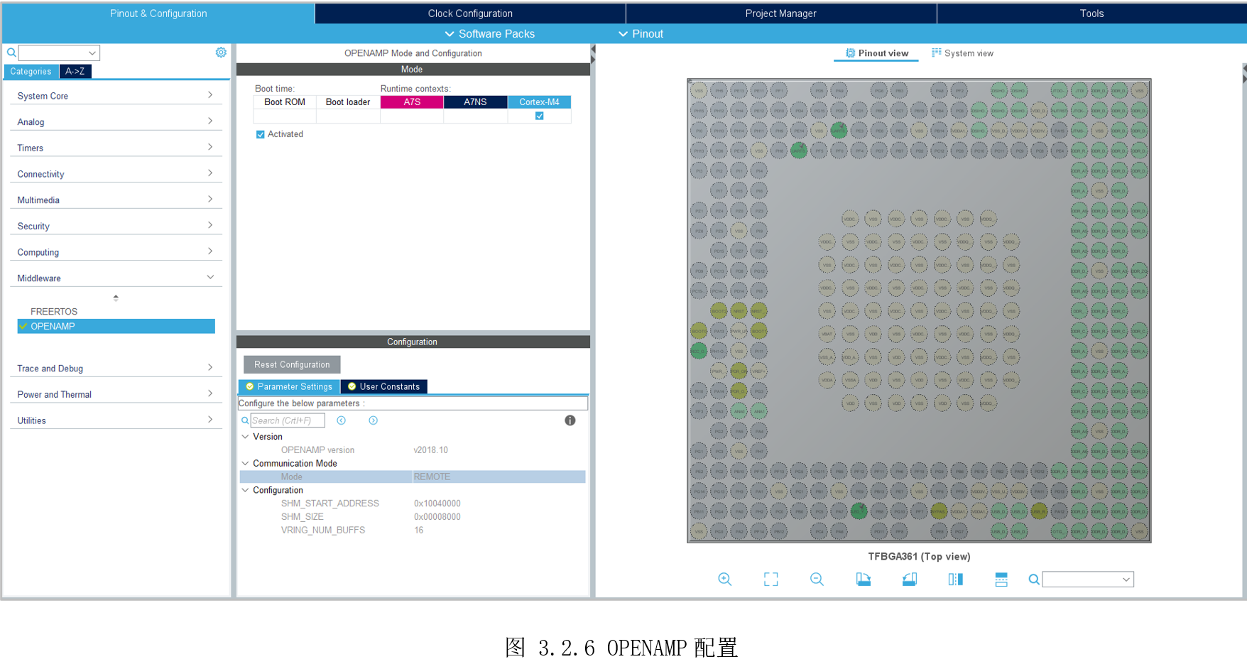
最后,勾选OPENAMP给M4,如图 3.2.6所示。
3.2.4 代码设计
生成初始化代码后,在主函数末尾附近,找到“USER CODE BEGIN 4”和“USER CODE END4”,在之间添加printf的重定向函数,让UART8与printf绑定。
/* USER CODE BEGIN 4 */
#ifdef __GNUC__

#define PUTCHAR_PROTOTYPE int __io_putchar(int ch)

PUTCHAR_PROTOTYPE
{

  HAL_UART_Transmit(&huart8, (uint8_t*)&ch, 1, HAL_MAX_DELAY);
  return ch;
}
#endif/* USER CODE END 4 */
- Setp 1: 初始化两个RPMsg tty虚拟串口
   if (VIRT_UART_Init(&huart0) != VIRT_UART_OK) {
      printf("VIRT_UART_Init UART0 failed.\r\n");
     Error_Handler();
   }
   if (VIRT_UART_Init(&huart1) != VIRT_UART_OK) {
      printf("VIRT_UART_Init UART1 failed.\r\n");
     Error_Handler();
- Setp 2: 注册回调函数以按通道接收消息
   if(VIRT_UART_RegisterCallback(&huart0, VIRT_UART_RXCPLT_CB_ID, VIRT_UART0_RxCpltCallback) != VIRT_UART_OK)
   {
    Error_Handler();
   }
   if(VIRT_UART_RegisterCallback(&huart1, VIRT_UART_RXCPLT_CB_ID, VIRT_UART1_RxCpltCallback) != VIRT_UART_OK)
   {
    Error_Handler();
}
- Setp 3: 编写虚拟串口回调函数
当RPMsg收到数据后,将调用该回调函数。在此函数里,需要将接收的数据复制到用户内存,并修改接收标志位,通知用户完成数据接收。
void VIRT_UART0_RxCpltCallback(VIRT_UART_HandleTypeDef *huart)
{
    printf("Msg received on VIRTUAL UART0 channel:  %s \r\n", (char *) huart->pRxBuffPtr);
    /* copy received msg in a variable to sent it back to master processor in main infinite loop*/
    VirtUart0ChannelRxSize = huart->RxXferSize < MAX_BUFFER_SIZE? huart->RxXferSize : MAX_BUFFER_SIZE-1;
    memcpy(VirtUart0ChannelBuffRx, huart->pRxBuffPtr, VirtUart0ChannelRxSize);
    VirtUart0RxMsg = SET;
}
void VIRT_UART1_RxCpltCallback(VIRT_UART_HandleTypeDef *huart)
{
    printf("Msg received on VIRTUAL UART1 channel:  %s \r\n", (char *) huart->pRxBuffPtr);
    /* copy received msg in a variable to sent it back to master processor in main infinite loop*/
    VirtUart1ChannelRxSize = huart->RxXferSize < MAX_BUFFER_SIZE? huart->RxXferSize : MAX_BUFFER_SIZE-1;
    memcpy(VirtUart1ChannelBuffRx, huart->pRxBuffPtr, VirtUart1ChannelRxSize);
    VirtUart1RxMsg = SET;
}
- Setp 4: 主函数轮询RPMsg消息
“OPENAMP_check_for_message()”查询MailBox状态。
当收到数据时,“VIRT_UARTx_RxCpltCallback()”会保存好收到数据,然后修改VirtUartxRxMsg标志位。主函数里发现VirtUartxRxMsg标志位发生变化时,即可获取接收的数据。
while (1)
{
   OPENAMP_check_for_message();
  /* USER CODE END WHILE */
  /* USER CODE BEGIN 3 */
  if (VirtUart0RxMsg)
  {
    VirtUart0RxMsg = RESET;
    /*VirUART0收到数据*/
  }
  if (VirtUart1RxMsg)
  {
    VirtUart1RxMsg = RESET;
    /*VirUART1收到数据*/
  }
}
- Setp 5: VirUART0接收控制LED指令
每次VirtUart0RxMsg发生变化,说明VirUART0收到了数据,然后比较收到的数据内容,执行对应的操作。
这里,M4收到“MSG_LED_ON(*led_on)”则打开LED灯,并发送消息给A7;M4收到“MSG_LED_OFF(*led_off)”则关闭LED灯,并发送消息给A7。
    if (VirtUart0RxMsg)
    {
      VirtUart0RxMsg = RESET;
      if (!strncmp((char *)VirtUart0ChannelBuffRx, MSG_LED_ON, strlen(MSG_LED_ON)))
      {
          strcpy((char *)BuffTx, "m4:led on\n");
          printf("%s\r", BuffTx);
          VIRT_UART_Transmit(&huart0, BuffTx, strlen((const char *)BuffTx));
          HAL_GPIO_WritePin(LED_YELLOW_GPIO_Port, LED_YELLOW_Pin, GPIO_PIN_RESET);
      }
      if (!strncmp((char *)VirtUart0ChannelBuffRx, MSG_LED_OFF, strlen(MSG_LED_OFF)))
      {
          strcpy((char *)BuffTx, "m4:led off\n");
          printf("%s\r", BuffTx);
          VIRT_UART_Transmit(&huart0, BuffTx, strlen((const char *)BuffTx));
          HAL_GPIO_WritePin(LED_YELLOW_GPIO_Port, LED_YELLOW_Pin, GPIO_PIN_SET);
      }
      memset(VirtUart0ChannelBuffRx, 0 ,VirtUart0ChannelRxSize);
      memset(BuffTx, 0 ,strlen((const char *)BuffTx));
}
- Setp 6:VirUART1接收休眠唤醒指令
每次VirtUart1RxMsg发生变化,说明VirUART1收到了数据,然后比较收到的数据内容,执行对应的操作。
这里,M4收到“MSG_STOP(*stop)”则进入CStop模式,中途A7再发任意数据给M4,由于IPCC也可设置为中断唤醒源,将M4唤醒;M4收到“MSG_DELAY(*delay)”则等待20S后发数据给A7,在这20S内,将A7先休眠,随后将被M4唤醒。
if (VirtUart1RxMsg)
    {
      VirtUart1RxMsg = RESET;
      if (!strncmp((char *)VirtUart1ChannelBuffRx, MSG_STOP, strlen(MSG_STOP)))
      {
          strcpy((char *)BuffTx, "m4:stop\n");
          printf("%s\r", BuffTx);
          VIRT_UART_Transmit(&huart1, BuffTx, strlen((const char *)BuffTx));
          //RCC_backupClocks();
          /* Clear the MCU flags before going into CSTOP */
          SET_BIT(PWR->MCUCR, PWR_MCUCR_CSSF);
          printf("Going to CStop mode\r\n");
          /* (C)STOP protection mechanism
           * Only the IT with the highest priority (0 value) can interrupt.
           * RCC_WAKEUP_IRQn IT is intended to have the highest priority and to be the
           * only one IT having this value
           * RCC_WAKEUP_IRQn is generated only when RCC is completely resumed from
           * CSTOP */
           __set_BASEPRI(1 << (8 - __NVIC_PRIO_BITS));
           HAL_PWR_EnterSTOPMode(PWR_MAINREGULATOR_ON, PWR_STOPENTRY_WFI);
           /* To allow Systick to increment after CSTOP (Eg.: to not block during
            * TIMEOUT routines), TICK_INT_PRIORITY < BASEPRI
            * For this example as TICK_INT_PRIORITY = 1, BASEPRI should be 2  */
           __set_BASEPRI(2 << (8 - __NVIC_PRIO_BITS));
           printf("Leaving CStop mode\r\n");
           /* Test if system was on STOP mode */
           if( (PWR->MCUCR & PWR_MCUCR_STOPF) == PWR_MCUCR_STOPF)
           {
              printf("System was on STOP mode\r\n");
              /* Clear the MCU flags */
              SET_BIT(PWR->MCUCR, PWR_MCUCR_CSSF);
              /* Restore clocks */
              /*
              if (RCC_restoreClocks() == HAL_OK)
              {
                  printf("CM4 restored clocks successfully\r\n");
              }
              */
            }
            /* All level of ITs can interrupt */
            __set_BASEPRI(0U);
      }
      if (!strncmp((char *)VirtUart1ChannelBuffRx, MSG_DELAY, strlen(MSG_DELAY)))
      {
          printf("Waiting 20 secs before sending the answer message\r\n");
          HAL_Delay(20 *1000);
          strcpy((char *)BuffTx, "m4:wakeup A7\n");
          printf("%s\r", BuffTx);
          VIRT_UART_Transmit(&huart1, BuffTx, strlen((const char *)BuffTx));
      }
      memset(VirtUart1ChannelBuffRx, 0 ,VirtUart1ChannelRxSize);
      memset(BuffTx, 0 ,strlen((const char *)BuffTx));
为了A7能发消息将M4唤醒,还需要IPCC作为M4的中断唤醒源。
 EXTI_ConfigTypeDef EXTI_ConfigStructure;
   EXTI_HandleTypeDef hexti62;
   /*
    * Set configuration of Exti line 62 (IPCC interrupt CPU2). It could be used to wakeup the
    * M4 from CStop mode when RPMsg received from Cortex-A7
    */
   EXTI_ConfigStructure.Line = EXTI_LINE_62;
   EXTI_ConfigStructure.Mode = EXTI_MODE_C2_INTERRUPT;
   //PERIPH_LOCK(EXTI);
   HAL_EXTI_SetConfigLine(&hexti62, &EXTI_ConfigStructure);
   //PERIPH_UNLOCK(EXTI);
   /*
    *     Enable RCC_IT_WKUP to exit M4 from CStop mode.
    *     Indeed, due to SOC issue, M4 firmware shall make sure
    *     RCC_WAKEUP interrupt is the first one used to exit M4 from CStop mode.
    *     Therefore, M4 masks all NVIC interrupts with priority higher than 0
    *     before entering CStop mode and unmasks them when moving from WFI.
    *     (in HAL_PWR_EnterSTOPMode function)
    *     Note: All other NVIC interrupts shall be set to a different value
    *     from 0 to make sure that this workaround works well.
    */
    __HAL_RCC_ENABLE_IT(RCC_IT_WKUP);
3.2.5 实验效果
编译程序,如图 3.2.7所示连接开发板。
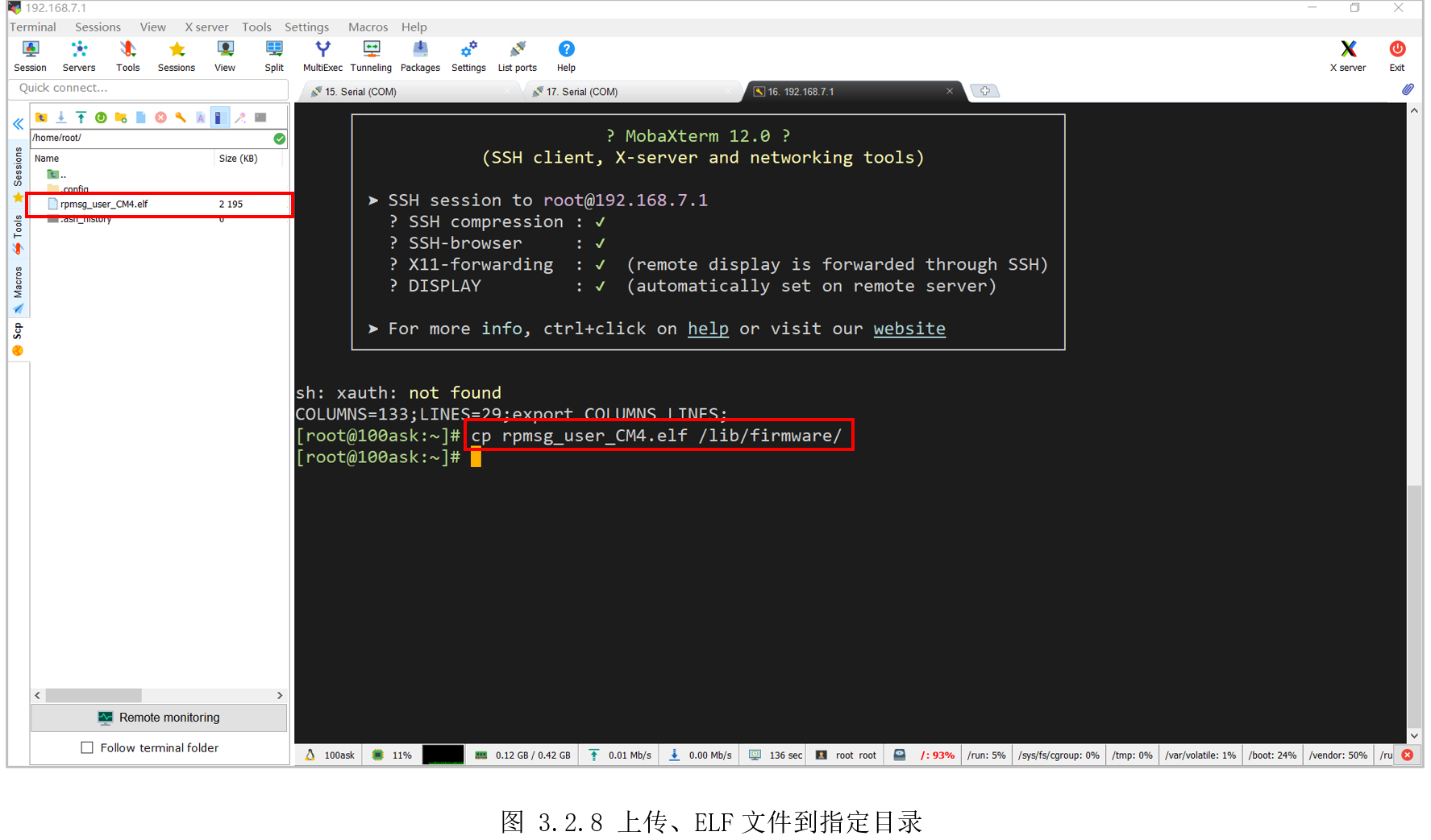
然后将前面生成“rpmsg_user_CM4.elf”,拖动上传到开发板Linux系统里,并执行“cprpmsg_user_CM4.elf /lib/firmware/”复制到“/lib/firmware/”目录里,如图 3.2.8所示。
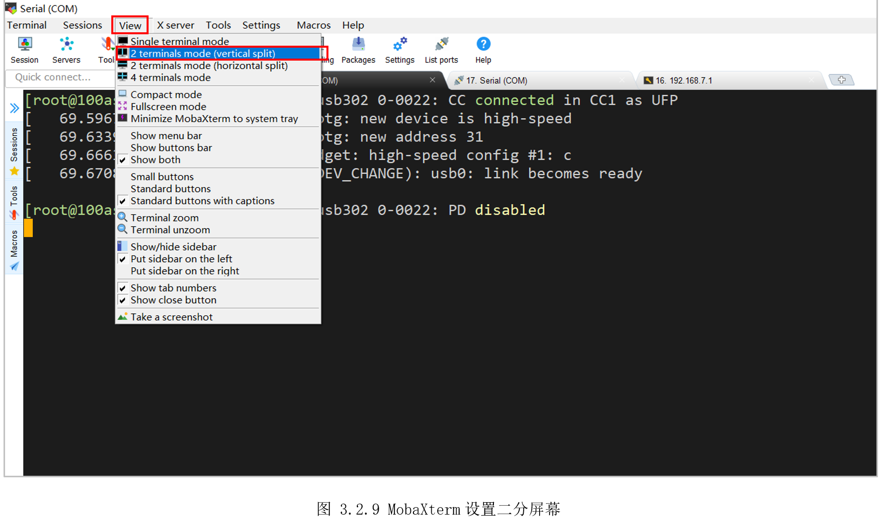
然后再打开M4对应的串口,为了方便同时查看A7和M4的打印信息,在MobaXterm上方选择2分屏显示,如图3.2.9所示。
效果如图 3.2.10所示,左边是Linux的串口终端,右边是M4对应的UART8调试串口。

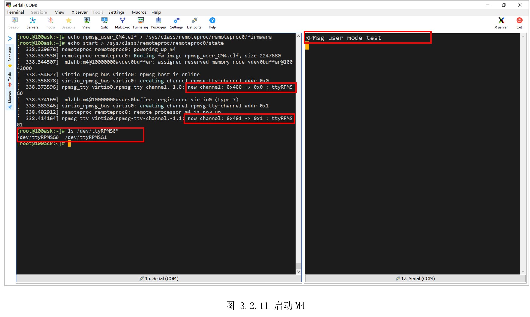
执行以下命令加载M4:
[root@100ask:~]$ echo rpmsg_user_CM4.elf > /sys/class/remoteproc/remoteproc0/firmware
[root@100ask:~]$ echo start > /sys/class/remoteproc/remoteproc0/state
随后打印可以看到启动了M4,并创建两个虚拟串口通道,生成了新节点“/dev/ttyRPMSG0”和“/dev/ttyRPMSG1”,右边M4也打印了启动信息,如图3.2.11所示。
接着需要输入以下两个命令设置下生成的虚拟串口“/dev/ttyRPMSG0”。
[root@100ask:\~]\$ stty -onlcr -echo -F /dev/ttyRPMSG0

[root@100ask:\~]\$ cat /dev/ttyRPMSG0 &
第一条命令里的“-onlcr”是不将NL字符映射为CR-NL字符,就是说发送给M4的数据,不会自动加上回车,不然这里发送“led_on”,M4收到的为“led_on\n\r”,“-echo”是禁止回显,以方便查看接收的字符。
第二条命令是后台运行查看“/dev/ttyRPMSG0”,一旦“/dev/ttyRPMSG0”收到数据,将立刻打印到当前终端。
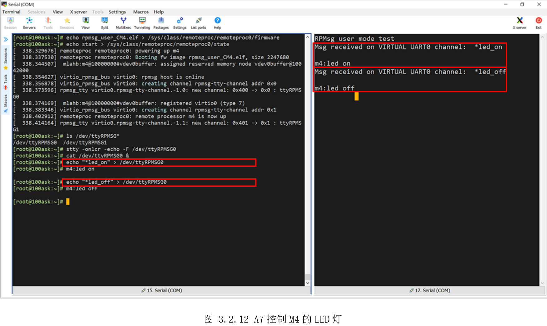
接着是向“/dev/ttyRPMSG0”写入预定义的指令,M4收到指令便会控制LED灯,并发送执行结果给A7,如图3.2.12所示。
[root@100ask:~]$ echo "*led_on" > /dev/ttyRPMSG0
[root@100ask:~]$ echo "*led_off" > /dev/ttyRPMSG0
执行以上两个命令,观察开发板LED,可以看到对应LED亮灭。
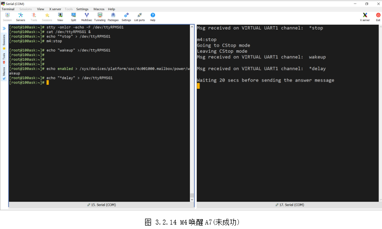
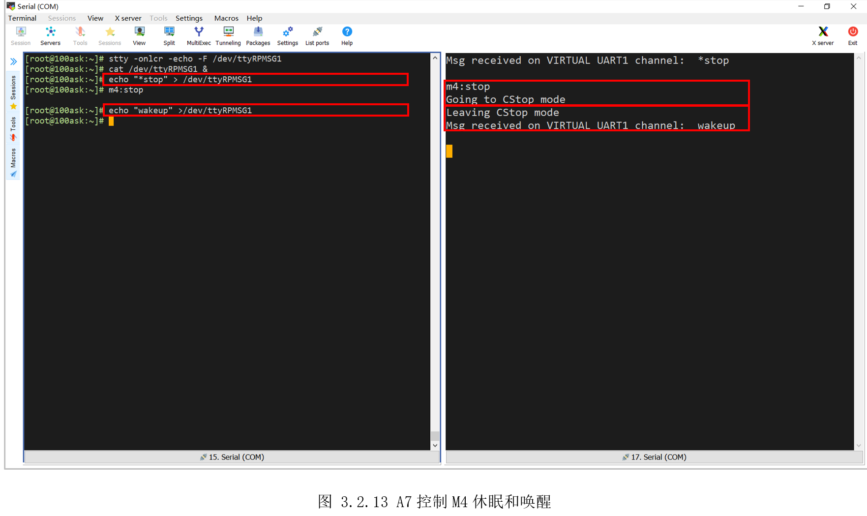
然后再测试A7和M4相互唤醒,先设置“/dev/ttyRPMSG1”。
[root@100ask:~]$ stty -onlcr -echo -F /dev/ttyRPMSG1
[root@100ask:~]$ cat /dev/ttyRPMSG1 &
然后向“/dev/ttyRPMSG1”写入“*stop”,M4随后卡在打印“Going to CStopmode”后,接着向“/dev/ttyRPMSG1”写入:“wakeup”(任意字符即可),M4随后打印“LeavingCStop mode”,即实现了A7控制M4的休眠和唤醒,效果如图 3.2.13所示。
[root@100ask:~]$ echo "*stop" > /dev/ttyRPMSG1
[root@100ask:~]$ echo "wakeup" >/dev/ttyRPMSG1
再测试M4唤醒A7。先使能A7唤醒,然后向“/dev/ttyRPMSG1”写入“*delay”,M4收到指令后,20S后会向A7发数据,从而唤醒A7。此时控制A7进入休眠状态,20S后,A7被唤醒。
[root@100ask:~]$ echo enabled > /sys/devices/platform/soc/4c001000.mailbox/power/wakeup //使能唤醒
[root@100ask:~]$ echo "*delay" > /dev/ttyRPMSG1  //通知M4一会唤醒自己
[root@100ask:~]$ echo mem > /sys/power/state  //A7进入休眠
注意,由于当前Linux休眠唤醒驱动bug,A7唤醒会复位重启,这里后期解决后,用户可再进行本实验,但这不影响本小节主题,A7和M4通信完成。